 Index
Index
- Bird Line Sections
- Comparisons
- Contact Information
- Custom Meter Scales
- Customizing MB-1
- Documentation
- Downloads
- Expansion Features
- Evaluating Analog Meters
- Evaluating Couplers
- FAQ
- Features
- Generic Meter and RF current Measurements
- Hardware Diagnostics
- Interfacing your own Analog Meters
- Interfacing your own Couplers
- Multi-Coupler Display Feature
- Prices
- Programming MB-1
- Projects
- Quick Reference Guide - Menus
- Quick Reference Guide - Switches and LEDs
- Recent Site Updates
- Reviews
- Specifications
- Simulator
- Troubleshooting
- Useful Links
- Using Different Couplers
- Utilities
- Videos
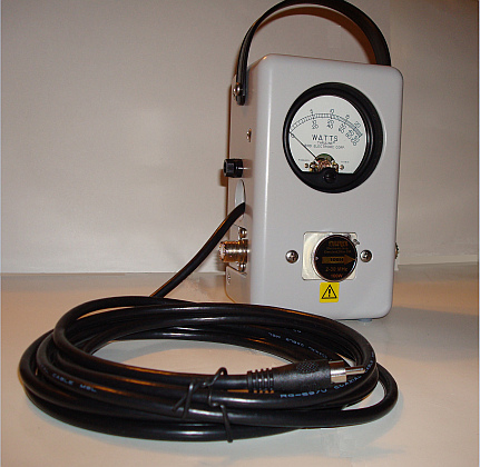
Need a second coupler for your MB-1? If
you have
a Bird Meter or Line Section, you can interface it
to MB-1and get excellent accuracy and resolution over
the full legal power limit with just a single Bird slug.
With the MB-1 Band correction feature, you can
even band correct the HF slug to cover 6 meters.
The notes below provide background
information on interfacing your Bird Line section and elements to MB-1. A
description is also provided on downloading and updating the MB-1 OEM
calibration tables that contains the preloaded calibration table for the Bird
100H Bird slug. Since there will be some variability between your Bird element
and the one we used to generate the calibration table, you will always get best
results by doing a custom calibration with your slug with an accurate reference.
If you decide to do your own calibration, the description below also contains
instructions on a simple procedure for using your MB-HF1 coupler in conjunction
with a DMM as an accurate reference source.
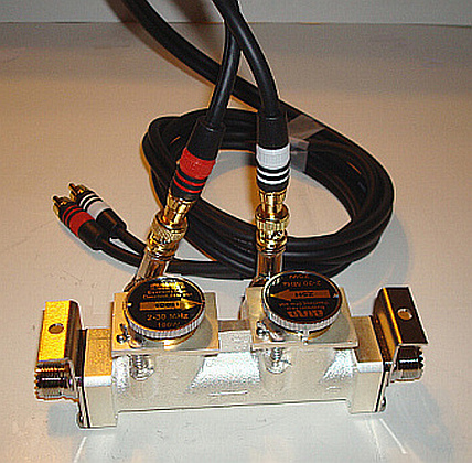
If you want to skip the background information and read the details of interfacing your Bird Line Section to MB-1, click the Single or Dual Bird Line links directly below.
Bird Single Line Sections
|
Bird Dual Line Sections
|
Overview:
Bird analog meters and slugs are ubiquitous, and cover the gamut of frequency ranges and power ranges up to 50,000 watts. But accuracy is specified at full scale only. By interfacing your Bird slugs to MB-1, and calibrating them with MB-1's custom calibration feature, you can obtain excellent accuracy over the entire power range and have access to all of MB-1's advanced features.
The calibration pot inside an HF Bird slug provides a single calibration point, which presumably is set at the full scale rating of the slug. On the other hand, MB-1 allows you to calibrate any coupler, including Bird elements, at up to 49 discrete power points within the legal power limit, and is therefore capable of calibrating the entire power range, from .05 watts to 1500 watts, and delivering accurate measurements across that power range.
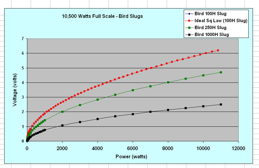
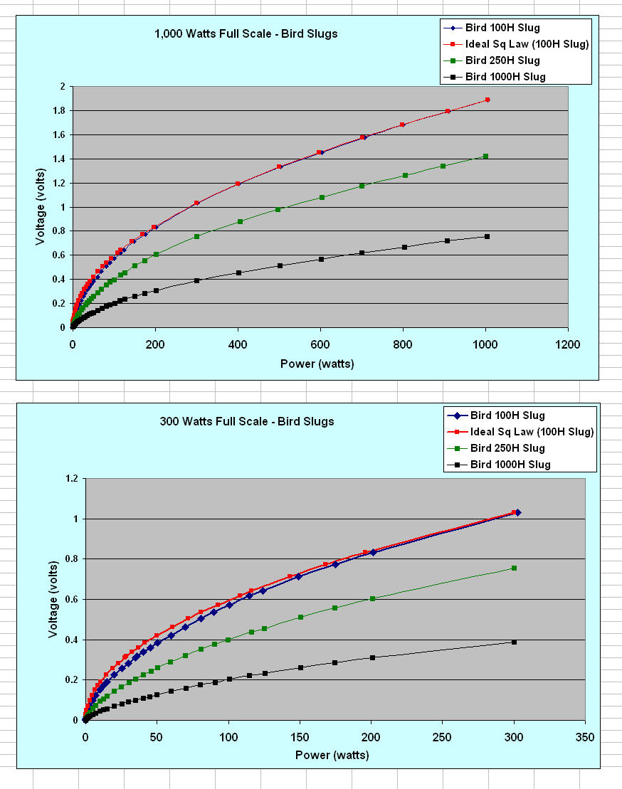
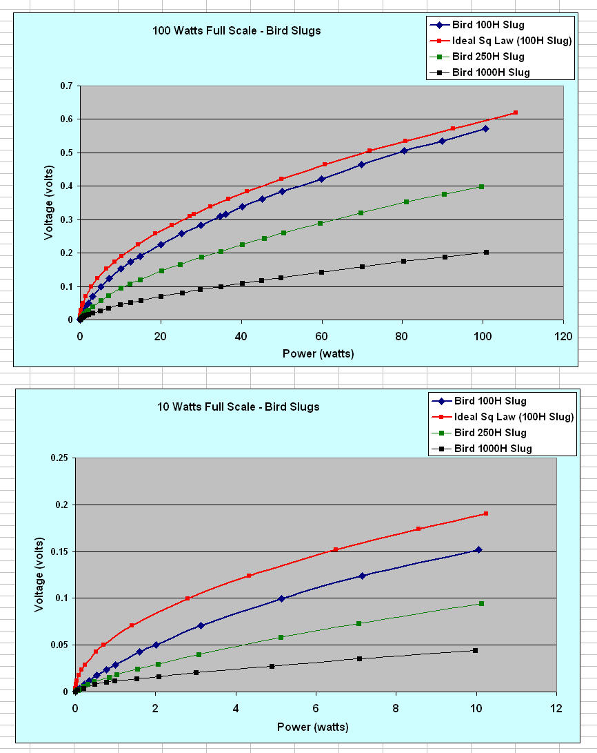
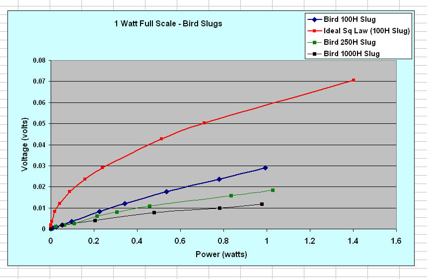
Graphs for three different Bird HF slugs (100 watts, 250 watts, and 1000 watts) are shown below. As can be seen from the graphs, the lowest power slug (100 watts) provides the most sensitivity (volts DC per watt). If you do your own custom calibration with a Bird 100 watt element using the MB-1 calibration feature, you can obtain tracking to within 2% of the reference meter you use for calibration over the entire power range, with the possible exception of the bottom 2% of the scale (where the DC sensitivity of the slug is too small to guarantee the same level of accuracy). Of course, your accuracy will be only as good as your reference. The higher power slugs (250w, 1000w) can be used as well, but with reduced resolution. Therefore, for interfacing to MB-1, we suggest that you use a 100 watt element. You could use a lower power slugs for more sensitivity, but while a 25 watt slug that we measured was more sensitive than the 100 watt slug, the difference in sensitivity was not substantial.
You may have noticed that elsewhere on the website, we stated that MB-1 can be calibrated to within 1% of a reference source when doing a custom calibration, so why the 2% rating with Bird slugs?. The 1% spec applies to couplers that can generate at least 6 volts full scale, since such couplers can take advantage of MB-1's full 15 bit resolution. However, the 100 watt Bird slug produces approximately 1.9 volts at 1000 watts (or approximately 2.7 volts at 2000 watts). Therefore, the Bird slugs will operate with somewhat reduced resolution (but still more than 13 bits, which is better than the 12 bit rating of some of the other digital meters). When testing how closely a Bird slug actually tracks the measurement reference after being calibrated with MB-1, the majority of measurements actually fell within the 1% limit, and so you can consider the 1% rating to be typical, but not guaranteed.
If you interface your Bird line section to MB-1, you can use a single Bird HF slug to cover the entire legal limit , and can also extend the range of that single HF slug to cover 6 meters as well using MB-1's Band Correction feature. Since the MB-1 calibration feature simply calibrates the coupler (or slug in this case) to the measurement reference used for the calibration, the slug you use does not even have to be within specs as long as it is stable. This can be useful if you have picked up used slugs at a hamfest or from an "as-is' online auction.
The Bird line section connects to the MB-1 with no intervening interface circuitry, and no modifications are required to your Bird wattmeter (or line section) either. And finally, by interfacing your Bird line section to MB-1, you can take advantage of MB-1's advanced features.
The following discusses the tests we performed on various Bird elements, and provides the basis for the claims made above.
The Bird element transfer function (power vs. voltage) is somewhat atypical. The curve in blue below shows the measurements that we made on a new 100H (100 watt HF) Bird element inserted in a Bird 43 line section. Measurements were made from .05 watts to 1000 watts using a high impedance digital multimeter with the Bird meter movement disconnected (i.e., we measured the slug's open circuit voltage). For comparison, the curves in red show the ideal square law curve assuming an idealized coupler (a perfect diode), normalized to the Bird curve at the 1000 watt point. You will find that the meter scales of many popular analog power meters, as well as the nominal published coupler curves for one of the Digital RF power meters, follow the idealized square law curve fairly closely for a good portion of the supported range. Thus the Bird element is not typical because it deviates from the ideal over much of its operating range. (This is the case even if we normalize the idealized curve to the Bird curve at 100 watts.)
We have also included graphs for the 250 watt and 1000 watt slugs. As is expected, these slugs produce a lower DC voltage for a given power level than the 100 watt slug.
As you probably already noted, we are using the 100 watt element in this example at power levels higher than the Bird rating. The ability to use Bird slugs at power levels significantly higher than the Bird rating was the topic of a QST article ("Getting Rid of Slugs", September, 2006). According to the QST article, for a given frequency range, the difference between Bird slugs with different power ratings is the value of the slug's calibration resistor that is placed in series with the 30 uA meter movement. (Our tests also show that the sensitivity of the slugs also varies as a function of power.) Therefore, the conclusion from the article is that you can run Bird slugs at higher power levels than their rated values.
As mentioned earlier, and as can be seen from the following curves, the Bird transfer function and the ideal square law power/voltage curve) are substantially different, especially under 300 watts. In fact, for very low power levels (power < 1 watt), the voltage-power relationship is essentially linear, as shown in the last graph. For higher power levels (power > 300 watts), the voltage-power relationship closely approaches the idealized square law curve. Above 1000 watts, the two curves are essentially the same. This last fact enables power levels up to 10,500 watts (and even higher) to be measured with MB-1 even though the largest calibration point measured for this exercise was 1000 watts.
For a detailed analysis of how the Bird elements operate over different power ranges, see K9SO's excellent article on this topic.
The Bird 43 wattmeter simply accounts for the Bird element's transfer function (in combination with its series calibration resistor) by designing the meter face to match the transfer function. Since the MB-1 multipoint calibration feature is designed to capture an arbitrary coupler transfer function over its entire power range, it is perfectly suited to capture the Bird transfer function as well.
If you do not have access to an accurate reference, you can download and install the calibration table we have created for the 100 watt Bird slug. This calibration table consists of 32 calibration points done with a newly NIST certified MiniCircuits 6GHS. Following calibration, the Bird slug provided excellent tracking with our reference over the entire power range (again, with somewhat less accuracy on the bottom 2% of the range).
Because of variations between slugs however, if you
have access to an accurate reference, you will achieve the best accuracy
by doing a custom calibration. You can also use the MB-HF1 coupler in
combination with a digital multimeter as a an accurate reference as
described
below.
Open Circuit Voltage vs. Power for various Bird Slugs
 |
 |
 |
 |
Interface Details:
When being driven from a Bird slug, the voltage across the 1400 ohm Bird 30 uA meter movement is not adequate to drive the MB-1 input circuitry. The voltage across the meter coil at the full scale rating of the slug is only 30 uA * 1400 ohms = 42 millivolts . However, the DC output from the slug, when unterminated (disconnected from the meter movement) is adequate to drive MB-1 directly. For example, the Bird output voltage at 1000 watts was measured at 1.89 volts with the 100 watt HF Bird slug.
The 100 watt Bird slug was calibrated with a NIST calibration standard, and then added to the MB-1 OEM calibration tables. If you do not plan to do your own calibration, this calibration table can downloaded from the MeterBuilder download page and loaded into your MB-1. The calibration table covers the 0 - 1000 watt range for the HF bands + 6 meters.
As mentioned above, the 100 watt HF slug generates a voltage of approximately 1.89 volts with 1000 watts applied when the DC output of the line section is unterminated. But MB-1 still has more dynamic range on its coupler input port (up to 6.14 volts max with the trim pot set at maximum sensitivity). MB-1 can therefore measure a maximum power of approximately 1,000w * [6.14 / 1.89]2 = 10,500 watts, which is more than adequate for Amateur use.
And as the above curves show, since the Bird element essentially follows the ideal square law curve for power levels above 1000 watts, the MB-1 extrapolation rule for power measurements that are larger than the largest power point calibration was performed at (1000 watts in this example) should provide accurate results. If desired, additional calibration points above 1000 watts can be added to the MB-1 calibration table by the user, but this is not required. And no band correction is required for the entire HF spectrum since this is one of the luxuries provided by the Bird slug!
While not of direct interest to the Amateur Radio community, its should be noted that the 10,500 watt limit mentioned above applies when the MB-1 coupler trim pot is set to its most sensitive setting. Power levels much higher than 10,500 watts can be measured by simply setting the coupler trim pot to provide some attenuation of the line section's DC voltage prior to calibration. MB-1s maximum numeric limit is 30,000 watts, but if required, that limitation is easily overcome by simply using a xN multiplier during calibration and operation. In reality, the line section hardware, including the connectors, will set an upper limit on the maximum practical power limit that can be used with a Bird line section.
Procedure for Installing the Updated MeterBuilder OEM Calibration Table on to your MB-1
If you want to use the calibration table generated by MeterBuilder for the 100H slug, you can download and install the Bird calibration table that we created. Think of this as analogous to the pre-loaded coupler table that is included with MB-1 for the MeterBuilder MB-HF1 coupler. These calibration tables are plug and play (with the exception of adjusting the coupler trim pot). Remember that this calibration table applies to the 100 watt HF Bird element.
Updating your MB-1 with the Bird calibration is a two step operation:
1. First, you must download an updated OEM calibration table that contains the new Bird calibration table. You must then copy it into the OEM section of EEProm on your MB-1.
2. Once the OEM EEProm table has been updated, you simply need to decide which of MB-1's four coupler ports you wish to use with the Bird line section and element. (You probably do not want to pick coupler port 1 since that is preloaded with the MB-HF1 calibration table). You then go into Setup for that coupler, and load in the new OEM table using the OEM code we have assigned to the BIRD table (3).
Adjust the trim pot for the selected coupler to its maximum sensitivity, and you are ready to go. The details are given below.
Verify the MB-1 to PC
connection:
To download the updated OEM table that contains the Bird calibration table, you must use the MB-1 OEM
calibration update utility, which is described
here and in the
User Manual,
section 11.3. To use this utility, you need to have the TeraTerm
terminal emulator (version 4.64)
installed on your PC. The installation instructions for TeraTerm are
given on the Download page.
Also, if not done already, make sure to run the RS-232 MB-1 Transmit and RS-232 MB-1 Receive self tests as described under the Self-Test menu in section 3.18 of the User Manual. Do not attempt to run the OEM update utility until you have verified that these two self tests run successfully. If the communication self tests fails, the utility will fail as well.
Download the OEM utility and data file:
Download this
Zip file into
an empty directory on your PC. This zip file contains the new OEM table
as well as the OEM utility that you will
run on your PC to load the new OEM table into your MB-1 EEProm. Unzip the zip file. You
will see two files: the PC utility (mb1_oem_update.ttl, which is
a TeraTerm macro developed by MeterBuilder that copies the data file
from your PC to MB-1), and the
data file that will be loaded into EEProm (mb1_oem.data). The
latter file is the one that contains the Bird calibration table.
Load the new OEM data file into your MB-1:
The EEPROM Backup/Restore menu (section 11.3 and section 3.11
in the User Manual), is used to load the new OEM data file from your PC
into your MB-1.
This makes use of the EEPRM-RST-O menu. The following lists the
steps to both update the OEM table and to load the Bird calibration
table into one of the four
MB-1 coupler ports (1-4):
-
Update the OEM section of EEPROM by using the mb1_oem_update.ttl Coupler Update Utility described above (using the EEPRM-RST-O menu).
-
Make sure that the coupler menu is the active menu (line 4 of the LCD). Enter the Coupler calibration Setup routine for the coupler number (1 - 4) corresponding to the coupler port you will connect the Bird Line section to. This is done with a long push of the Set-Up button.
-
Once in the setup routine, make sure to select the correct coupler number (1-4) you wish to use with the Bird line section. You do not want to overwrite the wrong coupler by mistake.
-
If asked to "Erase Old Settings" (which means that a previous coupler table is already loaded in this coupler slot), answer YES.
-
When asked if the coupler being calibrated is an OEM coupler, answer YES. This means that you will be skipping the detailed calibration steps, and will just be loading in a preloaded OEM table.
-
When asked to specify the OEM code, enter 3 (which is the OEM code for the Bird calibration table).
-
Save the settings. You have now loaded the Bird calibration table into one of MB-1's coupler tables.
The above procedure is much simpler than
it sounds. If you have TeraTerm installed, and your MB-1-to-PC
communication is working, it is a 10 minute procedure. If you need
help setting this up, we can do it over the phone.
Using the MB-HF1 Coupler to calibrate a Bird Element
If you want to do a custom calibration on your Bird element, but do not have an accurate reference meter, you can use the MB-HF1 coupler and a digital voltmeter as shown in the figure below. The MB-HF1 couplers have all had very closely matched transfer functions, so your MB-HF1 coupler should follow Table 1 closely. This table is the Power/voltage curve for the MB-HF1 coupler that is shipped with MB-1. You can provide a correction factor by dividing the benchmark voltage for the 500 watt point (printed on your coupler) by 18.04, which is the benchmark for the Table 1 values. Then multiply all of the voltages in Table 1 by this ratio. The correction factor should be relatively small (close to 1).
The DMM measurement should be performed with the MB-HF1 coupler unterminated (not plugged into MB-1).
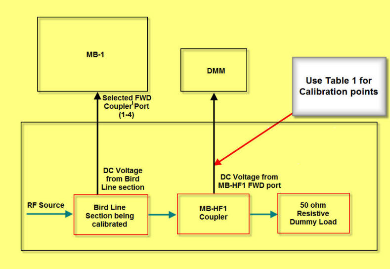
Table 1 - MB-HF1 Voltage vs. Power Power (watts) Voltage (volts) .05 .126 .1 .199 .2 .302 .3 .382 .5 .500 .8 .650 1 .681 2 1.065 3 1.318 4 1.543 5 1.737 10 2.488 20 3.545 50 5.718 100 8.163 150 10.001 200 11.406 500 18.040 1000 24.916
Bird Single
Line Sections
Bird Dual Line Sections
Bird FAQs