 Index
Index
- Bird Line Sections
- Comparisons
- Contact Information
- Custom Meter Scales
- Customizing MB-1
- Documentation
- Downloads
- Expansion Features
- Evaluating Analog Meters
- Evaluating Couplers
- FAQ
- Features
- Generic Meter and RF current Measurements
- Hardware Diagnostics
- Interfacing your own Analog Meters
- Interfacing your own Couplers
- Multi-Coupler Display Feature
- Prices
- Programming MB-1
- Projects
- Quick Reference Guide - Menus
- Quick Reference Guide - Switches and LEDs
- Recent Site Updates
- Reviews
- Specifications
- Simulator
- Troubleshooting
- Useful Links
- Using Different Couplers
- Utilities
- Videos
Generic Meter Applications
Programming MB-1 to work with Analog Sensors
Overview:
The discussion below describes how to use MB-1 with analog sensors to measure a variety of parameters (RF current, temperature, pressure, distance, pollutant concentrations, etc.). Just about any type of quantity can be measured if there is an analog sensor for that parameter that generates a DC voltage and meets MB-1's interface requirements. This capability was added to MB-1 by generalizing the 60 point calibration setup routines so that an analog sensor's transfer function could be mapped and stored in a coupler calibration table in a manner analogous to how a power coupler's transfer function is generated and stored.
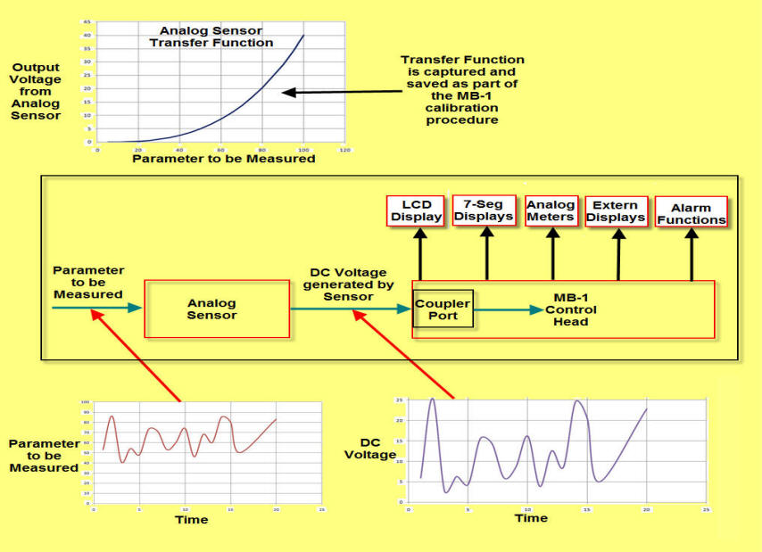
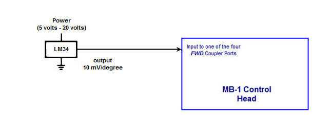
To see how MB-1 accomplishes Generic Measurement functions, refer to the diagram below. The parameter to be measured is first processed by an appropriate sensor, and the DC voltage from the sensor is then fed into the FWD port of one of MB-1's four coupler ports. That coupler port is then calibrated as a "Generic Meter Application" (vs. an RF power coupler), effectively providing a mapping of the transducer's transfer function. An example of a sensor transfer function is shown in the top graph in the figure below.
Once calibrated, MB-1 reads the sensor's output voltage and calculates the corresponding value of the parameter being measured. It then outputs the measurement to one or more of MB-1's configurable display devices. In addition to displaying the measurement, the parameter being measured can also be processed by other MB-1 features such as the Min/Max function, the peak capture function, the averaging function, and the alarm trip functions.
Sample Application:
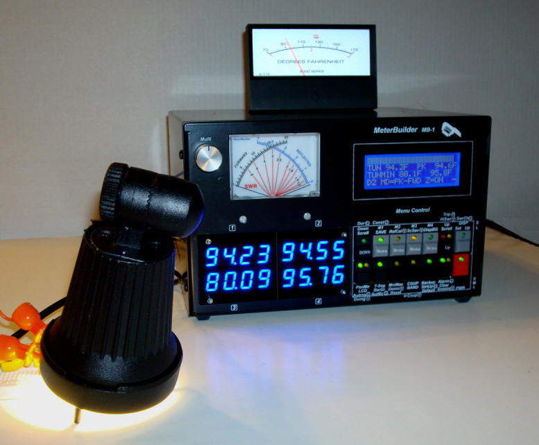
A sample application that uses an inexpensive temperature sensor is shown below. The sensor's output voltage is fed into one of MB-1's coupler ports after that coupler port has been calibrated to convert the voltage output from the sensor to a temperature value. In addition to displaying the temperature on various MB-1s display devices, the temperature is also processed by MB-1's Min/Max feature and alarm feature.
Temperature Sensor:
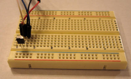
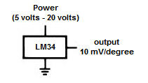
The temperature sensor, a National semiconductor LM34, shown below, and is being powered from MB-1's auxiliary 5 volt supply, which is accessible from two RCA jacks on the rear panel of the meter. The LM34 output is connected to one of MB-1's FWD coupler ports that has been calibrated to measure temperature.
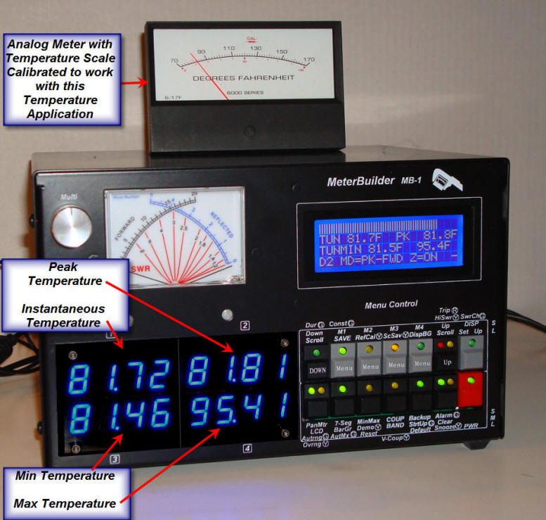
The photo below shows the temperature being displayed on the
internal 7-segment LEDS and an analog meter with a temperature
scale. The meter has been calibrated to work
with this application using the MB-1
Panel Meter calibration routines.
The photo below shows the MB-1 alarm function being used with this temperature application. The high temperature threshold has been set at 85 degrees. The halogen lamp, which serves as a heat source, is wired in series with the normally closed alarm contacts. When the relay trips, the contacts open, removing power from the lamp.
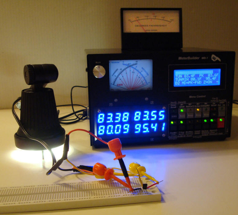
In the photo below, the heat source is placed close to the temperature sensor. When the alarm trips, power is removed from the lamp. In this example, the alarm is configured in the Auto Reset mode with a reset interval of 25 seconds. Therefore, 25 seconds after the alarm trips, the alarm automatically resets, reapplying power to the lamp. The sequence repeats indefinitely.
Overview on Programming a Generic Meter Application
To program a Generic Application with MB-1, connect the DC output signal from your analog sensor to the "FWD" port of one of MB-1's four coupler inputs. When you calibrate that coupler port, set the coupler type to "Generic". Define the full scale value and the "units character" that you want appended to the measurement values displayed on the LCD (e.g., V for volts, F for Fahrenheit, etc). Then run through the calibration process as spelled out in detail in the MB-1 User's Manual.
If the sensor for your application has a linear relationship between the parameter being measured and the voltage generated by the sensor, and if the transfer function starts at the origin (0, 0), a single calibration point is all that is required. If the DC voltage has a nonlinear relationship or does not pass through the transfer function's origin, you need to perform the calibration at multiple points. Several examples are given in the "MB-1 - Programmable Meter for Analog Sensors" Manual.
The MB-1 Configuration Set feature can be very useful when switching between different applications, whether they are Amateur Radio applications or are applications interfacing to analog sensors. For example, if you program an analog sensor, you can select the coupler port being fed by the sensor, the analog meter you wish to display the sensor's measurements on, the Alarm trip threshold points, and any other parameters specific to that application. You can then save those settings into a Configuration Set. The next time you want to use MB-1 for that application, simply recall that Configuration Set. Likewise, if you have saved your RF power meter settings in a different Configuration Set, you can easily revert back to RF power meter operation the same way - by simply recalling its Configuration Set.
You can also program MB-1 to measure RF current. This is covered below.
You can mix and match any four power meter, RF Ammeter, or
Generic Applications with MB-1 (you are limited only by the four
coupler ports).
Calibration Procedure
The data sheet for the LM34 can be found
here . The device
generates a DC output voltage that is directly proportional to
the temperature in Fahrenheit (10 millivolts per degree). We use
the LM34D, which has a range of 32° to 212°. This corresponds
to an output voltage of 320 millivolts to 2.120 volts for the
full temperature range.
National Semiconductor LM34 Temperature Sensor
Connecting the Temperature Sensor to MB-1
The calibration steps are spelled out in detail in the User's Manual. We outline them below to give you a general idea of how the calibration procedure works.
- Select an unused coupler port (1 - 4) and set the coupler type to
"Generic".
- Since we are measuring degrees in Fahrenheit, in the
setup screen, set the
Units character to “F”. The "suffix" character
specified in this step will be
appended to measurements displayed on the LCD (just like the
character "w" is displayed for RF for power
measurements for watts).
- Set the coupler port to an appropriate full scale value.
In this example, we us a full scale value of 170, which
corresponds to the maximum value that can be displayed on
the external analog meter. Other values could have been
chosen to take full advantage of the sensor's range - for
example, a full scale value of 212 or 220 could have been
selected.
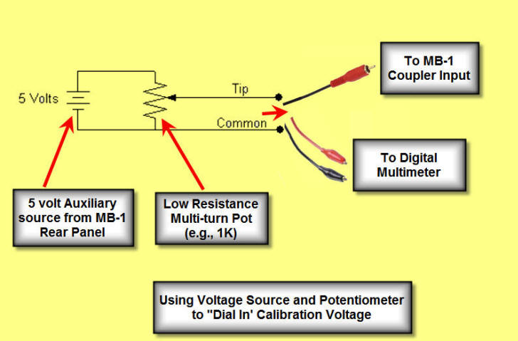
- Apply a source of 1.00 volt to the FWD port of the coupler
being calibrated. This is most easily done by connecting a
stable DC voltage across a potentiometer, adjusting the
potentiometer's wiper output to 1.0 volt as measured with any high
impedance voltmeter, and then feeding the 1.0 volt signal
into the coupler port. The 5 volt auxiliary power output on the
rear panel RCA jacks is suitable for powering an external
pot for this purpose. If you use a low resistance
potentiometer (e.g., 1 K), you don't need to worry about the
loading of the coupler port. The figure below shows an
arrangement that can be used for calibrating an analog
sensor application whose transfer function is known.
- Save the calibration data at a single point - 100°. (This corresponds to the 1.00 volt being applied in the step above.) That calibration point is then saved as
part of the coupler's calibration table in EEProm.
Since the LM34D input device has a linear characteristic
that passes through the origin,
calibration is required at a single point only.
- Complete the calibration by saving the calibration table
into EEProm.
- Connect the LM34 as shown above. Since the power demands of the LM34 are low, you can also use the rear panel auxiliary 5 volt power source to power the LM34. Your MB-1 should now be displaying the ambient temperature in degrees Fahrenheit.
Measuring RF Current with MB-1
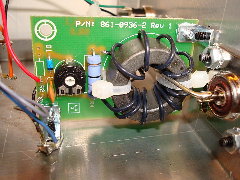
An RF Current Sensor is really just another type of analog sensor (with some minor variations as outlined in the User Manual). Below is a picture of an RF Current sensor from an MFJ RF current meter that has been calibrated with MB-1. You will also find several circuits for RF current sensors on the Internet. They are relatively easy to build.
Calibrating an RF Sensor:
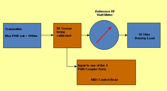
If you have an accurate reference RF ammeter, you can
place it in tandem with the RF sensor to be calibrated.
Alternatively, an accurate RF power meter can be placed in
tandem with the current sensor as shown in the figure below and
the current can be calculated using power measurements. This
is probably the more readily available solution for most of us.
In fact, if you are willing to calibrate a single current point
at a time, you can set the RF power level first using the MB-HF1
coupler, and then calibrate a single current point for the RF
sensor. Using the Coupler Setup EDIT function, you can then repeat
these steps for each calibration point.
Configuration for Calibrating an RF Current Sensor
Multiple values are selected in the table
below to ensure that the RF current sensor is adequately
characterized
over its low, medium, and high operating ranges.
Power-Current Calibration Points
|
RF Current Calibration Point (Amps) |
Corresponding Power |
|
0.1 |
0.5 watts |
|
0.5 |
12.5 watts |
|
1 |
50 watts |
|
2 |
200 watts |
|
3 |
450 watts |
|
4 |
800 watts |
Restrictions
To use MB1’s Generic Meter features, the sensor or transducer output must meet the following requirements:
- The parameter you wish to measure must be a DC voltage, or must be converted to a DC voltage.
- The voltage level must be within the dynamic range of the coupler ports. The trim pots allow you to easily scale down sensors with large DC outputs. If the available DC voltage from the sensor is very low, an amplifier can be added and the amplified output can be fed to the MB-1 coupler port.
- The source generating the voltage must share a common ground with MB-1.
- The voltage must have a positive polarity.
- The DC voltage must increase monotonically as a function of the parameter being measured
If the sensor you want to use does not meet one or more of the above requirements, it may be possible to develop an interface circuit to resolves the issue. The interface circuit would be placed between the sensor and the coupler input. Many such examples are covered in the User Manual.
Some Analog Sensors for Generic Applications
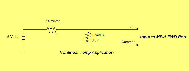
Sparkfun, Pololu, Adafuit, and RobotShop have a number of sensors for a large variety of applications ranging from simple temperature sensors to more exotic sensors such as alcohol gas level sensors, flex sensors, and gyroscopes. Some of these sensors provide a direct DC output voltage that can be fed directly into the coupler port of MB-1. Others change their resistance as the parameter varies. The latter type can be used with MB-1 by placing the sensor in series with a fixed resistor, feeding MB-1 from the voltage divider tap formed by the sensor resistance and the fixed resistance, and powering the series connection from a DC source as shown in a thermistor application in the figure below. Depending upon how the sensor resistance varies with the parameter, the sensor can either be connected between the voltage source and the tap of the fixed resistor (as shown below), or between the tap of the fixed resistor and ground. The choice should be made so that the voltage fed to the MB-1 coupler port increases as the parameter being measured increases.
Please note that MeterBuilder has experimented with just a few of these sensors so please read the sensor data sheets and make sure you understand the MB-1 restrictions to determine if a particular sensor will work satisfactorily for your application.