Index
Index
- Bird Line Sections
- Comparisons
- Contact Information
- Custom Meter Scales
- Customizing MB-1
- Documentation
- Downloads
- Expansion Features
- Evaluating Analog Meters
- Evaluating Couplers
- FAQ
- Features
- Generic Meter and RF current Measurements
- Hardware Diagnostics
- Interfacing your own Analog Meters
- Interfacing your own Couplers
- Multi-Coupler Display Feature
- Prices
- Programming MB-1
- Projects
- Quick Reference Guide - Menus
- Quick Reference Guide - Switches and LEDs
- Recent Site Updates
- Reviews
- Specifications
- Simulator
- Troubleshooting
- Useful Links
- Using Different Couplers
- Utilities
- Videos
Hardware Diagnostics
MB-1 includes interactive hardware and software diagnostics that are started using the SELF-TST Menu. As an example, when the front switch test is run in the diagnostics test, the LCD prompts you to press each of the front panel switches one at a time. As each switch is pressed, if the switch press is recognized by the software, the switch number is displayed on the LCD. All major functions are tested in a similar way. The different self test categories are listed below:
- Processor, memory tests, and peripheral chips.
- Display devices (LCD, panel meters and panel meter drive circuits, Internal 7-segment LED displays, External 7-segment display, External Bar Graph Module)
- Coupler inputs and Programmable Gain Amplifier/A-to-D Chain
- Front Panel Switches including Switch LED indicators
- Front Panel Hi Precision Pot
- RS-232 Transmit/Receive
- Piezo Sounder
- Alarm Relay
- These diagnostics are particularly useful after assembly of the meter, but they can be be run at any time to verify proper operation of the meter. Problems identified by the diagnostics, in conjunction with the circuit description and troubleshooting page, should simplify any required troubleshooting.
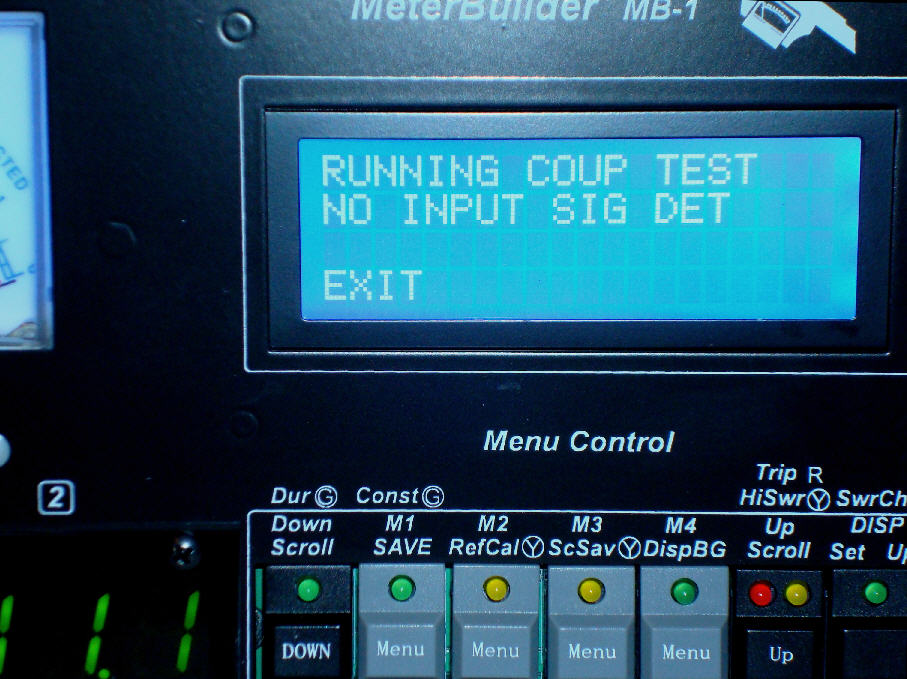
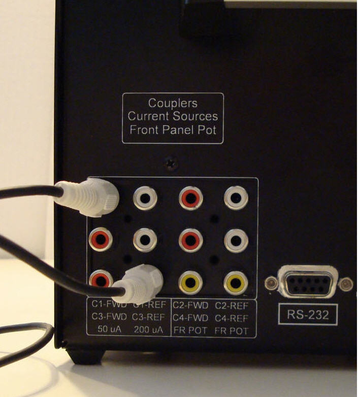
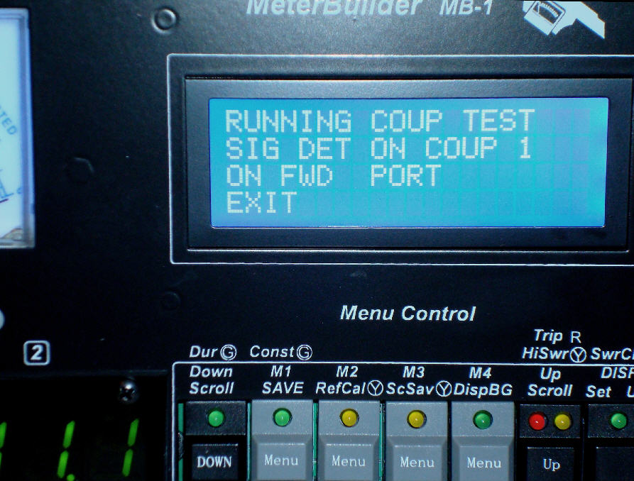
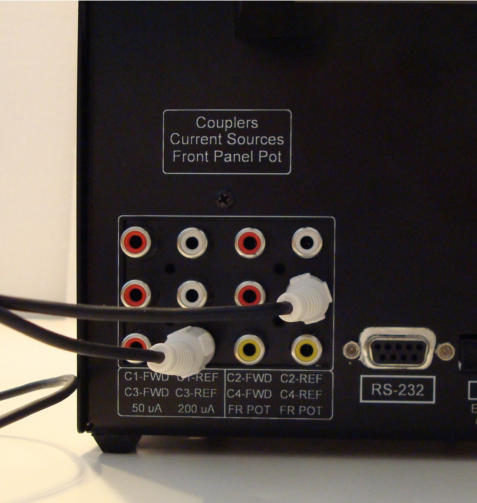
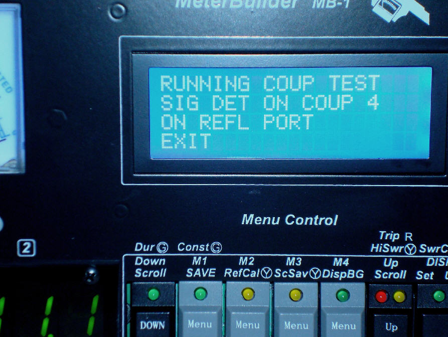
The self test procedure for the Coupler Port/Amplifier Chain test is shown below. In this test, an RCA cable is connected between the 200 uA RCA jack and each of the eight coupler port input jacks, one at a time. The 200 uA source simply provides a readily available DC signal source that should be detectable by the coupler port input circuitry. As signals are detected on each coupler port, the detected port number is displayed on the LCD. The piezo sensor is also sounded in case troubleshooting is required without the LCD display being readily visible.
The Hardware Diagnostics are described fully in the User's Manual
Coupler/Amplifier Chain Test
No Signal Applied |
||
|
|
||
Signal Applied to FWD Port on Coupler 1 |
||
|
|
|
|
Signal Applied to REFL Port on Coupler 4 |
||
|
|
|
|