| As with all Set-Up functions,
first display the applicable menu on line 4 of the LCD (Coupler Menu). Then press the
Set-Up button (Top Right Button - Long press). |
 |
|
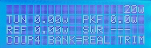
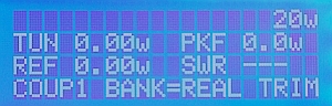
| Select Coupler:
The software will enter the coupler calibration setup routine
bringing up the screen to the right. Press the UP or DOWN buttons
(M1 or M2) to select the Coupler you want to calibrate. (In this example,
coupler 4 has been selected) Then press SELECT (M3).
Make sure you use the UP/DOWN "buttons"
represented by the first two menus choices on the top line of the
LCD using the MENU-1 and MENU-2 buttons, and not the buttons with
the Up-Scroll and Down-Scroll silkscreen labeling.
|
 |
|
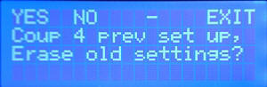
| Erase Settings? If the
Coupler that you selected was previously calibrated, you are given
the option to erase the previous settings or to EDIT the current
settings.
If you want to perform a new calibration as we do here,
press YES (M1) to erase the old settings. If, instead, you
wanted to EDIT the settings of a previous calibration, you would
press NO (M2)
Since we are doing a new calibration, we do not use the EDIT function in this
example, but the EDIT prompt (had you chosen NO) is displayed at the end of this table
for completeness. |
|
|
| Select Calibration Type: This
screen specifies the type of calibration to be performed on the
selected coupler port. The choices are PWR (RF Power
Coupler), AMPS (RF Ammeter coupler), or GENER (when
using MB-1 with Analog Sensors). Since we are calibrating a power coupler, select
PWR (M1).
|
 |
|
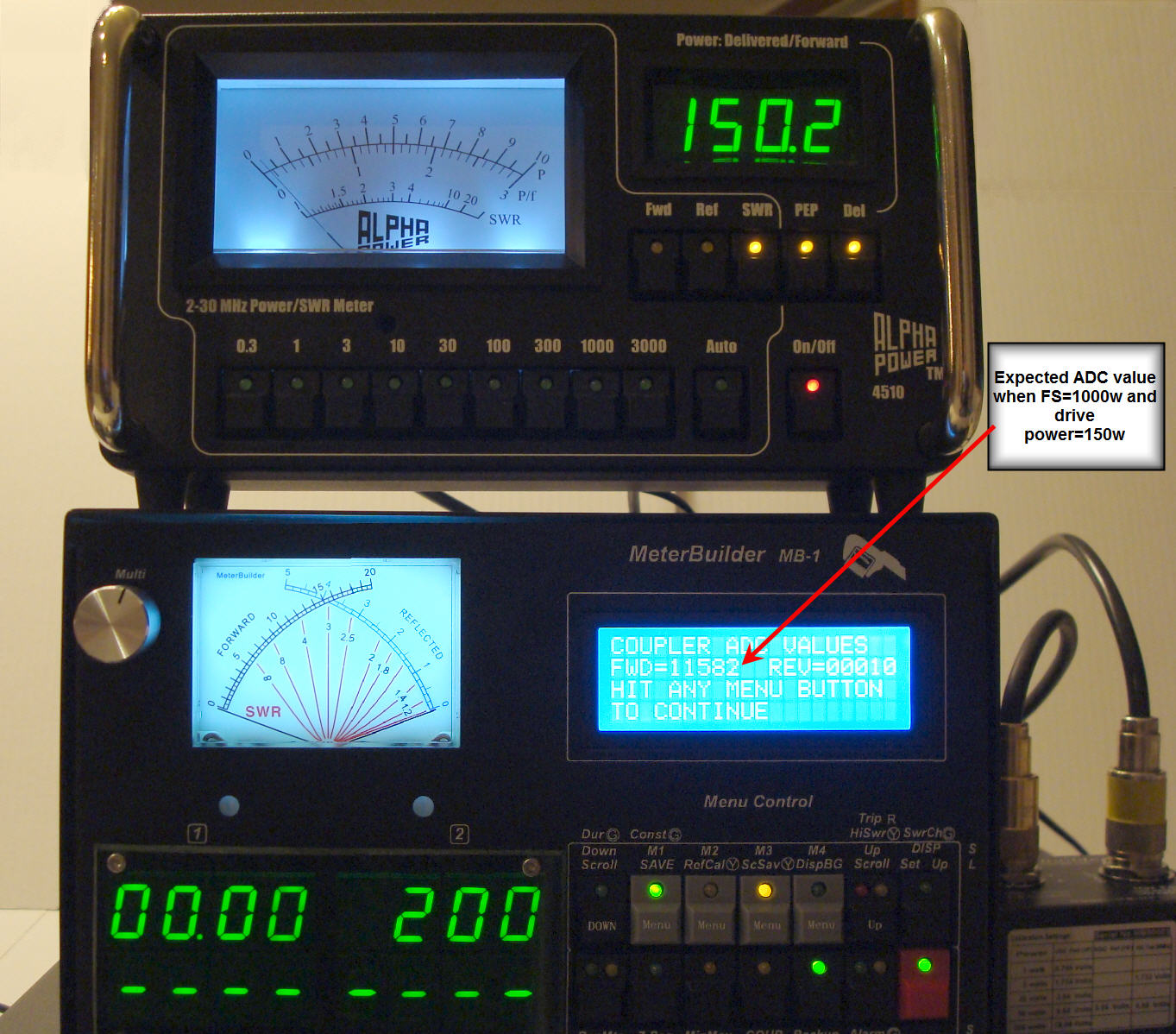
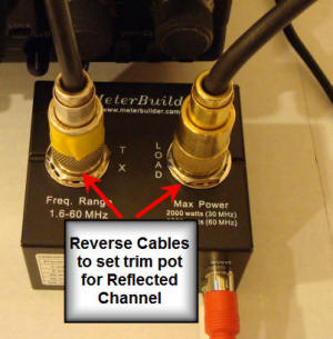
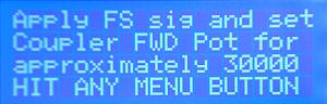
| Adjust FWD Coupler Trim Pot:
The screens on the right aid in adjusting the coupler's FWD port trim pot for
maximum sensitivity without overdriving the Amp/Mux in MB-1.
Typically, to adjust the FWD port trim pot, you set the transmit
power to the full scale value you want to calibrate the coupler at
(which would be 1000 watts in this example), and
then adjust the FWD trim pot until the FWD ADC reading on the LCD
reads
approximately 30,000 - a value slightly below the max Amp/Mux 15 bit value of
32,736 to guarantee some margin.
However, since we do not have a transmitter capable of outputting 1000 watts
in our sample setup,
we consult the User's Manual to determine the value that should
be used to adjust the trim pot to when using a power level below the FS
value to adjust the coupler trim pot (This will likely be a typical case for many users.)
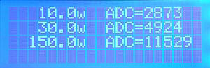
If you follow the formula in the User's Manual, when the desired FS value
of the coupler is 1000 watts, and the power being applied to adjust
the trim pot is 150
watts (a reasonable value for the Mark V), the FWD trim pot should be
adjusted to an ADC value of
approximately 11,600. This is an approximate setting. It is
important that you be in the "ballpark" only for this step. It is
better to err on the side of setting this value to a slightly lower
value since the goal of this step is to prevent overdriving MB-1's input
circuitry.
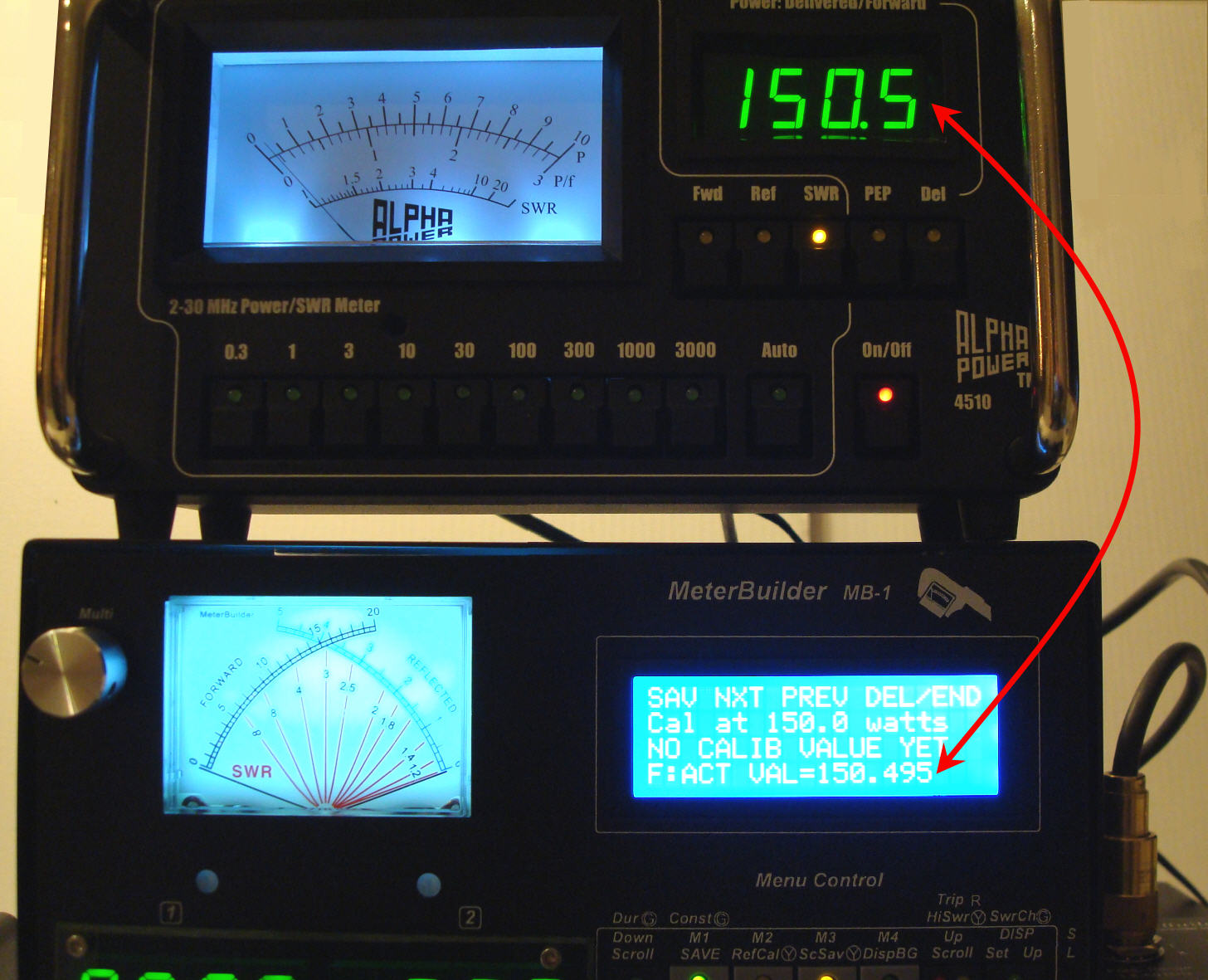
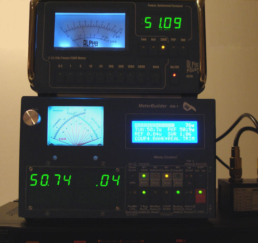
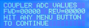
When the top screen in the right column is displayed, press any
menu button (M1 - M4) to display the actual FWD and REFL ADC values being
applied to the coupler FWD and REFL ports. This is shown in the
second screen. This screen shows the ADC values (0) with no power
applied.
The photo at the far right shows the screen when power is applied
and the FWD trim pot
is properly adjusted.
After adjusting the trim pot, remove transmit power. Then press
any menu button to continue.
|
|
Click to Expand

|
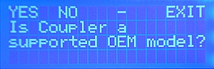
| OEM Option: The User's Manual
explains the details of the preloaded OEM tables. The MB-HF1
has its calibration table
preloaded in EEProm. If you are using this coupler (or other
couplers that may be supported by this feature in the future),
the entire calibration table, including any band
compensation calibration values, can be loaded into the
coupler port you are calibrating simply by answering YES to
this prompt, and then entering the OEM numeric code for the corresponding coupler.
This eliminates the need to perform the point by
point calibration steps listed below. (However, you still need to adjust the
FWD and REFL trim pots as per the manual.) Even though we could
have used the OEM option for the MB-HF1 coupler in this
example,
we will answer NO to this prompt so that we can demonstrate
the step-by step procedures below for performing a custom coupler
calibration.
|
 |
|
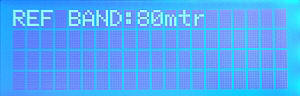
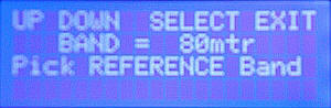
| Select Reference Band: Use
this screen to specify the Reference Band. This is the band
you will use when performing the FWD power calibration. If your
transceiver supports 80 meters, this is a good band to use. The "Reference Band"
holds the main calibration data, and is also used by the band
correction algorithms, since the correction table measurements for each band are made with
respect to the calibration point measurements performed in the Reference Band. |
 |
|
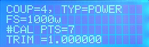
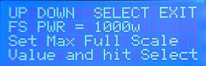
| Specify Full Scale Power:
This screen is used to specify the FS value you intend to use with
this coupler. This information is used to determine the list of
calibration points you will be offered during the calibration procedure.
(When we set the FS value to 1000 watts as shown to the right, no calibration points greater than 1000 watts will be offered for calibration
during the actual calibration sequence.)
This FS value is also used to set the Full scale value
that the Simulator will generate when the Simulator is used to generate
simulated values for this
coupler. |
 |
|
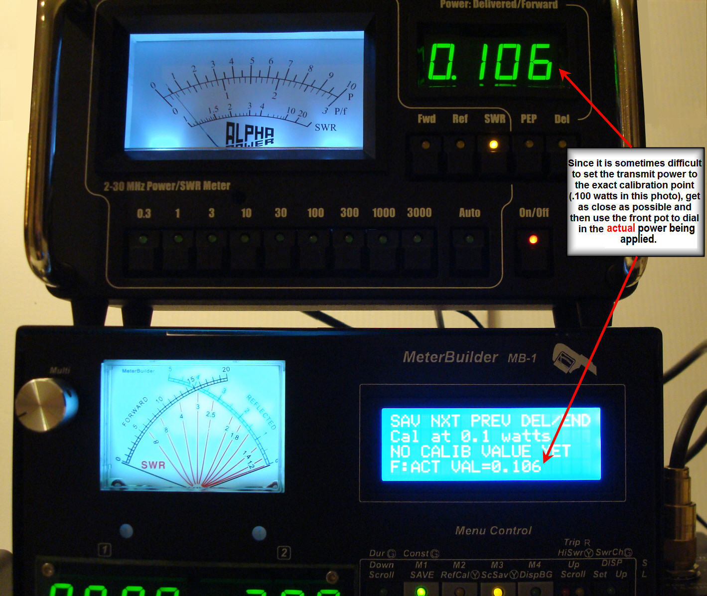
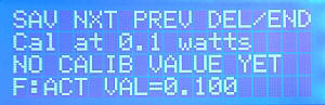
Actual
Calibration:
(Calibration shown at .1w Calibration point)
The software then displays a screen similar to the one on the
right for each calibration point,
starting at .05 watts, and ending at the calibration point closest
to the Full Scale power you specified above.To calibrate each
point, apply the nominal power as displayed on the LCD, using a
transmitter and reference meter.
Then press SAV (M1). The screens to the right show the prompt
and the reference meter reading for
the .1 watt calibration point.
Remember, you do not need to calibrate all of the calibration points
within the FS range that you specified, but you must perform a calibration at least
one power level for the software to consider the calibration valid.
To skip a calibration point and move to the next higher power
calibration point, simply press NXT (M2).
After each point is saved, the screen automatically advances to
the next available calibration point. Use the PREV (M3) button if you
need to go
back to lower power calibration point for any reason. Use the DEL (M3 -
short press) button to delete a calibration point (useful if you
know that a calibration point has a significant error, and you do
not want to recalibrate that point).
Note: You will achieve better accuracy by calibrating with a
smaller number of accurate calibration points rather than with a
larger number of poor quality calibration points.
|
 |
Click to Expand
 |
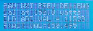
| End Calibration after last
calibration point: A photo of the final calibration point (150
watts) is shown in the far right column. (We are ending here since
we do not have a 1 Kw power source in this example.)
When you have saved the calibration data for all of the desired
power points, terminate the current calibration session
by pressing END (Long press to M4).
This will allow you to save the calibration points below.
Convention: All menu choices that
perform a single function (like SAV, NXT and PREV
in the menu to the right) are requested with a short push of the
corresponding menu button.
Since there are only four menu buttons (M1 - M4), those menus that have five
choices like the one shown to the right on line 1 of the LCD are handled as follows.
For this menu, the Last menu item DEL/END controls both the
DELete function and the END calibration function. For
these dual menu cases, you select the first function (DEL) with a
short press of the corresponding menu button (M4 in this case).
You select the second function (END) with a long press of the
corresponding menu button (M4).
|
|
Click to Expand
 |
| Perform Frequency Correction:
After ending the reference calibration, the screen to the right presents you with the option to perform Band
Calibration. Until you are comfortable with the basic (Reference
Band) calibration described here, it is suggested that you skip this
step by pressing NO (M2). You can EDIT this coupler
table at
a later time to add the band compensation points.
(Your coupler will still be useable on all bands, but will make use
of the single Reference Band calibration data in this case.)
Full details for performing Band calibration are given in the User's Manual. |
 |
|
| Save Prompt: The screen at the
right is the SAVE prompt. To save the calibration data to EEProm, press
SAVE (M1).
To abort without saving the current calibration data, press EXIT
(M4). |
 |
|
| Confirmation:
The screen to the right confirms that the calibration data was saved
to EEProm. |
 |
|
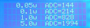
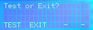
| TEST or EXIT: The software now
gives you the option to EXIT (resuming normal meter operation) or to
TEST the coupler. The TEST option displays the ADC
values corresponding to the DC voltages on the FWD and REFL ports of
the coupler. Think of this as a simple continuity check to verify that the
coupler you think is connected to this coupler port is actually connected
properly, and that the magnitude of the displayed ADC values
increase or decreases as power applied through the coupler increases
or decreases. |
 |
|
| |
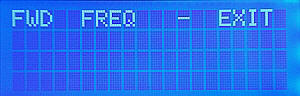
| In the example above, we performed a
new calibration. Had we chosen the EDIT option to edit the existing
calibration table (by answering NO to the ERASE request at
the beginning of the example), the
screen to the right would have been displayed.
To EDIT the existing FWD power calibration table (the Reference
Band), press FWD
(M1). This will bring you to the
actual calibration sequence
described earlier in the above example. Once in this mode, you can
select one or more previously calibrated points and recalibrate
them, or you can select power points that were not previously
calibrated, and include them in the coupler's calibration table.
To perform (or edit) band calibration, enter FREQ
(M2). Band calibration is covered in detail in the User's
manual. |
 |
|
 Index
Index