 Index
Index
- Bird Line Sections
- Comparisons
- Contact Information
- Custom Meter Scales
- Customizing MB-1
- Documentation
- Downloads
- Expansion Features
- Evaluating Analog Meters
- Evaluating Couplers
- FAQ
- Features
- Generic Meter and RF current Measurements
- Hardware Diagnostics
- Interfacing your own Analog Meters
- Interfacing your own Couplers
- Multi-Coupler Display Feature
- Prices
- Programming MB-1
- Projects
- Quick Reference Guide - Menus
- Quick Reference Guide - Switches and LEDs
- Recent Site Updates
- Reviews
- Specifications
- Simulator
- Troubleshooting
- Useful Links
- Using Different Couplers
- Utilities
- Videos
Evaluating Couplers for use with MB-1
This section provides some information on interfacing your own couplers to MB-1. The information below discusses those factors that will influence how well a coupler will work with MB-1. Almost any Bruene type coupler can be calibrated with MB-1 to provide very accurate Forward Power readings. The accuracy of reflected power measurements and SWR (which makes use of the reflected power measurement) is influenced by characteristics of the coupler as discussed below.
Once you are familiar with the MB-1 coupler calibration procedure, you may decide that it is easier to calibrate a candidate coupler with MB-1 and check its performance rather than running through the detailed tests below. But if you run into problems, you will likely find the source below.
Coupler Output Voltage at Full Scale:
With respect to forward Power
measurements, MB-1 can interface with almost any Bruene type coupler
that has a DC voltage
outputs. To utilize the full 15 bit resolution of MB-1, the coupler
must have a full scale output voltage of at least 6 volts. Most of the couplers
we have tried meet this limit. However, if the full scale voltage is
less than 6 volts, this simply means that you will be operating at
less than the full resolution. Even a .5v volt full scale output
will be useable, but a minimum of 2 volts full scale voltage is
probably a good rule of thumb for using a coupler with MB-1.
Full scale voltages larger than 6 volts are not a problem. Adjustment of the coupler trim pot
during calibration as per the User's Manual will ensure that the Amplifier/Mux
chain of MB-1 is not overdriven.
Minimum calibration power point (PMIN_CAL):
Even if the coupler you are using has a good full scale
DC output voltage, you may find that the coupler does not start to generate
any appreciable DC output voltage on the FWD port until the applied
power exceeds some minimum threshold (that we will call PMIN-CAL).
MB-1's lowest calibration power point is .05 watts. But if the
coupler does not start to generate any appreciable DC voltage until
the power is .2 watts for example, you should be aware of this, and
you should not attempt to calibrate MB-1 at any power points below
PMIN_CAL (in this example, .2 watts). MB-1 will still be able to provide
power measurements when the applied power is lower than PMIN_CAL
by approximating the coupler's power-voltage curve using the
calibration data for the lowest power calibration point,
but you should take any measurement readings in this range with a
grain of salt.
If you select the lowest power calibration point you will use during set-up to a power level where the coupler generates 25 millivolts of more, you should be OK. The included MB-HF1 coupler easily meets this requirement at the lowest power calibration point (.05 watts).
Coupler Quality and Calibration:
The directivity of a coupler is its "figure of merit".
It is a measure of how well the coupler isolates the forward and
reflected signals. The larger the number the better.
In most real world cases, the main impact of using a coupler with poor directivity will be inaccuracies in the SWR. Some couplers also have "nulling capacitors" that are adjusted at the factory. If these were not adjusted properly or have been misadjusted, this will impact the ability of the coupler to provide accurate measurements.
Unless you have used the coupler before and believe it to be working properly, the following is a quick stand-alone sanity check that you can perform.
-
Terminate the Load side of the coupler in a 50 ohm resistive termination.
-
Apply power well within the operating range of the coupler (e.g., 100 watts if the coupler is rated for 100 watts or greater).
-
Measure the DC voltage at the Forward port (VFWD)
-
Measure the DC voltage at the Reflected port (VREFL)
-
Calculate the SWR using the voltage formulas;
rho = VREFL / VFWD
SWR = (1 = rho) / (1 - rho)
With an ideal coupler, the calculated SWR should be perfect (1.0). Any real coupler will have a somewhat higher SWR. In practice, view this calculated SWR as the lowest SWR you will be able to read even when actual SWR of the load is perfect. Even couplers that do poorly in this test (e.g., calculated SWR > 1.3) can be used if you recognize that there will be some limitations in the SWR readings.
Note: We have come across a few couplers that actually generate a negative voltage on the Reflected port when running this test. The Reflected port DC readings start to look more reasonable on these couplers as the load mismatch increases. With respect to SWR measurements, the best we have been able to achieve with such couplers are mediocre results with respect to flat SWR measurements vs. power. Keep this in mind if you come across one of these couplers.
Coupler Square Law and Frequency
Response Characteristics:
For an ideal coupler, the voltage output should be proportional to
the square root of the applied power across the entire power and
frequency range. All real couplers fall short in this
respect. However,
by
making use of MB-1's multipoint calibration routines, even couplers
that have very poor voltage/power characteristics and power
voltage vs. frequency characteristics can be calibrated with MB-1 to provide
extremely accurate results.
FWD Port and REFL Port Tracking:
Poor tacking between the FWD port and REFL port will
result in variations in the calculated SWR value as a function of
the applied power level. Ideally, SWR readings should be independent of the power level.
Many couplers have very good tracking. Some do not. Below we
describe a MeterBuilder utility that you can use
to evaluate the FWD/REFL tracking. The utility, which can be
downloaded from the MeterBuilder website, uses a Microsoft Excel
spreadsheet.
To use the utility, you perform voltage measurements on both the FWD and REFL ports at a series of different power levels and then enter the measured results in the spreadsheet. A reference power meter needs to be placed in series with the coupler under test. The reference meter used for this exercise does not need to be particularly accurate since it is just being used to determine a power range, not an exact power value.
The measurements are performed at up to eight different power levels although the utility will make use whatever data you enter if measurements are performed at fewer than eight power points.
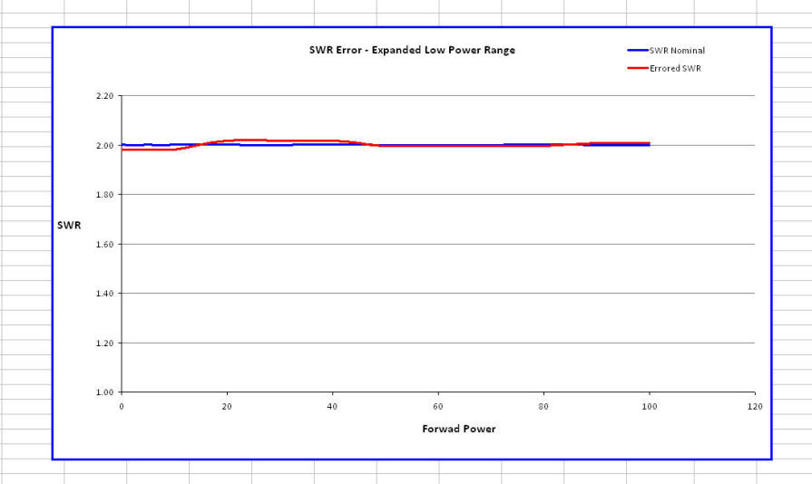
The utility uses the measured data to calculate the expected SWR value as a function of FWD power, and displays the results graphically. This tool gives an approximate piecewise linear approximation of how the SWR measurement will vary with power. Remember - this is a piecewise linear approximation only. Keep this in mind when using the utility.
For a coupler with a good match, the calculated SWR will be flat (vs. power) and will be close to the nominal value of the SWR. Large deviations from the nominal value indicate a mismatch in tracking, which will result in some variation in the SWR reading as the power is varied. This effect will be more pronounced for higher SWR values. (You can easily see this by experimenting with the utility and observing how a fixed %error between the FWD and REFL ports results in a larger variation in SWR values as the nominal SWR value increases.)
Using the FWD/REFL Tracking Utility
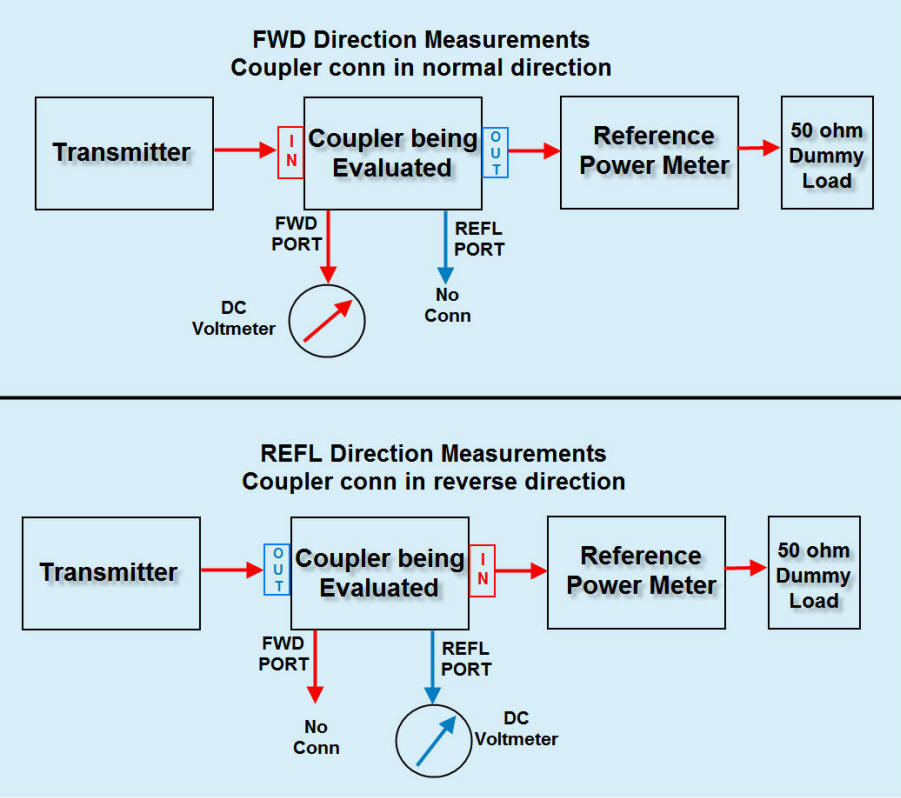
The figure below shows the setup to perform the voltage measurements required by the tracking utility. For both the top and bottom configurations in the figure below, the same power is transmitted. In the top of the figure, the coupler is connected in the normal direction with respect to the transmitter and load, and the voltage is measured at the coupler's FWD port. In the bottom of the figure, the coupler is reversed with the transmit power being fed into OUT/LOAD/ANT side of the coupler, and voltage is measured at the coupler's REFL port.
The above steps are repeated for a series of power measurements to cover the intended operating range.

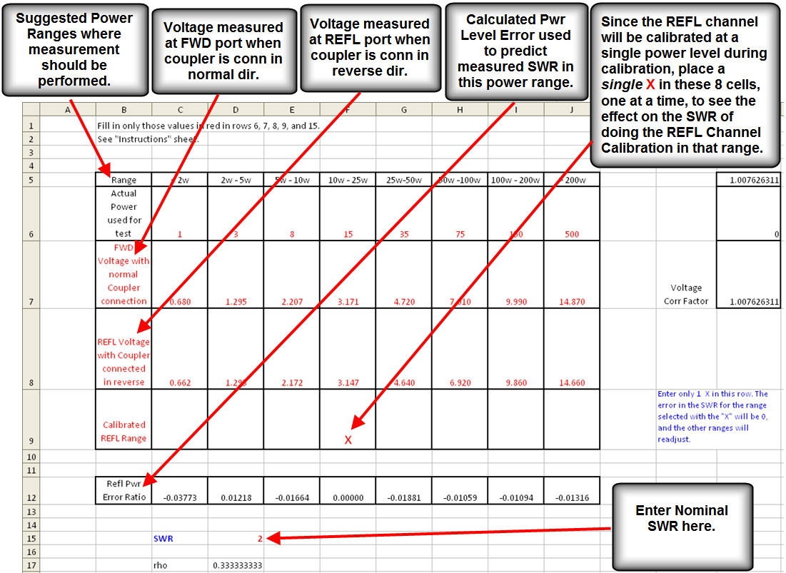
Entering Data in the FWD/REFL Tracking Utility
The utility is shown below. You enter your measurements in the rows labeled FWD Voltage and REFL Voltage (red font). You can also enter an "X" in the Calibrated Refl Range row. Since the REFL port will be calibrated at a single power level when you calibrate the coupler with MB-1, the SWR error at that power should be 0 (and will be shown as 0 for the entire range included by this power point because of the piecewise linear approximation).
By placing an X in a given power range, the utility will set the SWR error for that entire piecewise range to 0 and adjust the SWR values up or down accordingly for the other piecewise segments. If you have coupler with poor FWD/REFL tracking, you might be able to minimize the average SWR error by determining what the SWR curves look like when the REFL channel calibration is done at different power ranges (by moving the X to a different column). If you perform the REFL channel calibration at a power within the range that gives the best compromise, you will get the best results for SWR. Remember to use the REFL power corresponding to the range of the best fit, not the FWD power, which is the X axis value on the Excel graph.
The figure below shows where you enter the data for the FWD and REFL voltages. The REFL Power Error Ratio value is calculated from these values and used to calculate the SWR vs. FWD Power graph. For the best resolution, you should enter data values for each of the specified power levels (< 2w, 2w - 5 w, ...). Try to perform the measurements at a power level in the middle of each range (e.g., 1 watt for the < 2 watt case, etc.).
If the RF power control on your rig gives you fine control for repeatable measurements, you can perform all of the FWD measurements in one shot, noting the power used for each range. You can then reverse the coupler once and perform all of the power measurements for the reflected port after dialing in the corresponding power values used for the FWD measurements. However, if the RF power control does not allow you to easily duplicate the FWD power levels, you are better off setting the power level for a given range, and swapping the coupler direction for each of the eight (max) power levels to ensure that the FWD and REFL measurements were performed at the same power level.

Below, the red line is the FWD/REFL tracking curve for the MB-HF1 coupler for a nominal SWR value of 2.0. This coupler tracks very well.

Coupler Evaluation
Utility
Requires MS Excel
Examples of Other Couplers Being Used with MB-1
