 Index
Index
- Bird Line Sections
- Comparisons
- Contact Information
- Custom Meter Scales
- Customizing MB-1
- Documentation
- Downloads
- Expansion Features
- Evaluating Analog Meters
- Evaluating Couplers
- FAQ
- Features
- Generic Meter and RF current Measurements
- Hardware Diagnostics
- Interfacing your own Analog Meters
- Interfacing your own Couplers
- Multi-Coupler Display Feature
- Prices
- Programming MB-1
- Projects
- Quick Reference Guide - Menus
- Quick Reference Guide - Switches and LEDs
- Recent Site Updates
- Reviews
- Specifications
- Simulator
- Troubleshooting
- Useful Links
- Using Different Couplers
- Utilities
- Videos
Features:
A Fully Programmable Amateur Radio Power Meter.
Many of these features are unique to MeterBuilder.
- Program MB-1 to interface with up to four remote couplers with Full Scale power ranges from 1 watt to 30,000 watts in steps of 1 watt.
- Includes a Linear Scale Crossneedle Analog Meter with Real Time response capable of tracking voice and CW signals.
- Have multiple rigs at different locations in your shack? With the Expansion Kit, you can add up to two additional Crossneedle meters or up to four additional single needle meters, and place an analog panel meter at each station.
- 15 Bit effective low range Resolution.
- MB-1 does away with the need for proprietary couplers - Use MB1's Patent Pending Calibration Routines to reuse Existing Couplers - even Couplers in existing equipment.
- RF Ammeter - Use MB1-s calibration features to measure RF Current (requires an RF current sensor), or use MB-1's Patent Pending Generic Meter capability to interface to almost any analog sensor or transducer.
- Need a high-visibility numeric readout and bar graph display for easy viewing at a distance? Attach the Hi Visibility 7-Segment LED Display modules and Hi Visibility LED Bar Graph module.
- Auto-Max Bar Graph - Automatically adapts the Bar Graph's full scale value to the maximum encountered signal in 1 watt steps, eliminating the need to choose from a compromise set of fixed values.
- Six sets of backup/restore settings plus a factory default set give you single button backup and restore capability for all of your meter settings. Each backup set can give the meter an entirely different personality.
- Menus are interrupt driven. Once a menu is selected, meter configuration changes can be made on the fly using one of the four menu buttons without disrupting normal meter operation.
- All features are controllable directly from the front panel. No PC interface is required.
- Pre-loaded Calibration Table for the included MB-HF1 coupler
- Tutorial-style manual - Extensive Background Information in addition to operating instructions.
- Steel case with blind self-clinching fasteners on case front, and threaded inserts and machine screws for case assembly.
- Lots of other features you will find only in the MeterBuilder MB-1.
Some Comments on Accuracy
MB-1 has field Calibration capabilities not found in any other RF Power Meter. For field calibration, most other meters offer just one master trim point for the overall coupler alignment. And for those meters that provide field calibration for band correction, just one band correction trim point per band is provided. While MB-1 can be trimmed at a single power level as well, it offers up to 60 field adjustable master trim points, and up to 9 additional trim points per band. With careful calibration, this unique calibration scheme can provide an unmatched level of accuracy.
A Description of the MB-1 Calibration Algorithm
For an ideal coupler, the power is proportional to the square of the voltage generated by the coupler's detectors. However, real Bruene type couplers will always deviate from the ideal coupler for a number of reasons. The dynamic characteristics of the diodes used in these couplers is one source of errors. Even when operating in the diode's linear range, real couplers will deviate to some degree from an ideal coupler. In addition, couplers are generally not flat meaning that the voltage-to-power curve typically varies when the operating band (frequency) changes.
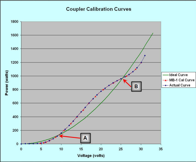
The figure below illustrates how the MB-1 calibration feature can be used to achieve excellent accuracy, even with a coupler that deviates substantially from the ideal. Three curves are shown. The green curve is a power vs. voltage curve for an ideal coupler. It follows the square law relationship exactly. The blue curve represents the curve for a hypothetical "real world" coupler. It shares two points, A and B, with the ideal coupler, but otherwise deviates substantially from the ideal curve. The deviation from the ideal curve has been exaggerated to challenge the MB-1 calibration routine's ability to track an arbitrary coupler curve, but deviations do exit and can be substantial (see Bird element transfer function for a real world example).
The red curve below is the resulting MB-1
calibration curve that results when calibrating the
real coupler with the MB-1 calibration feature at the following
power points:
10, 20, 30, 50, 100, 200, 300, 400, 500, 600, 700, 800, 900,
1000, 1100, 1200 watts.
For this exercise, it is assumed that the reference meter used
for the calibration is ideal and introduces no error into the
calibration.
As can be seen, even when a coupler has substantial deviation from the ideal, with 16 calibration points in this example, the MB-1 curve follows the real coupler curve almost exactly.

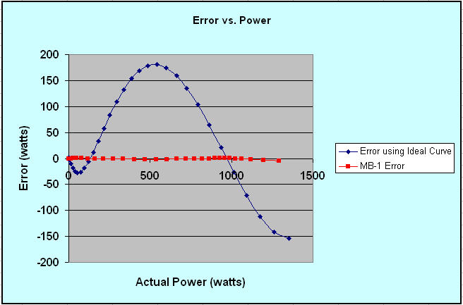
The blue curve in the figure below shows the error (actual power - measured power) that would result if a measurement algorithm was implemented assuming the ideal curve, and either point A or point B above was used to determine the constant of proportionality. Points A and B were chosen above since these points provide the correct power measurement when an ideal coupler is assumed, but choosing any other point on the real curve produces similar results.
The red curve in the figure below shows the error that results between the actual power and MB-1 measurements after the "real coupler" has been calibrated with the MB-1 calibration feature. When the incident power is exactly equal to one of the MB-1 calibration points, the error between the actual power and the MB-1 measurement is 0. However, the more typical case occurs when the incident power falls between two MB-1 calibration points. In this case, MB-1 uses the data from the bounded calibration points to compute a new best fit curve using interpolation. Therefore, when the power levels falls between calibration points, the MB-1 error will be nonzero as shown in the red curve below.
The bottom line of this example is that just about any Bruene type coupler can be calibrated with MB-1 to produce very accurate power measurements, even if its power/voltage curve deviates substantially from the ideal. The required number of calibration points for a given coupler is a function of how much the coupler curve deviates from the ideal. But with an adequate number of calibration points (16 in this example), the calibrated coupler will track the calibration reference to within 1%. This does require that the coupler being used has adequate sensitivity (at least 6 volts DC full scale), but this is not a problem with most of the couplers we have tested.

Band Calibration
To achieve the best accuracy, tests with several couplers suggest that band calibration needs to be performed at multiple power levels on each band, since tracking of power measurements compared to the reference band was observed to vary both as a function of frequency and power. For this reason, MB-1 provides a method of performing band correction at multiple power levels for each band.
The MB-1 Calibration feature is Patent Pending.
