 Index
Index
- Bird Line Sections
- Comparisons
- Contact Information
- Custom Meter Scales
- Customizing MB-1
- Documentation
- Downloads
- Expansion Features
- Evaluating Analog Meters
- Evaluating Couplers
- FAQ
- Features
- Generic Meter and RF current Measurements
- Hardware Diagnostics
- Interfacing your own Analog Meters
- Interfacing your own Couplers
- Multi-Coupler Display Feature
- Prices
- Programming MB-1
- Projects
- Quick Reference Guide - Menus
- Quick Reference Guide - Switches and LEDs
- Recent Site Updates
- Reviews
- Specifications
- Simulator
- Troubleshooting
- Useful Links
- Using Different Couplers
- Utilities
- Videos
External View
Front Panel
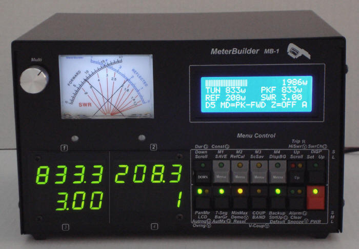
The front panel consists of the following:
Crossneedle Meter – Simultaneously displays Forward and
Reflected Power allowing the SWR to be read at the intersection of the two needles. The analog meter can also display peak, average, and
delivered power. For these modes, only the FWD needle is used.
The forward and reflected scales are linear - a
feature not generally found on crossneedle meter scales. The forward scale
can also be used for measuring RF current and for Generic Meter
functions using analog sensors.
7-Segment Displays – The meter contains four 4-digit 7-segment displays. Each Display can be individually programmed to display a different measurement or configuration value. (Examples of configuration values are the currently selected coupler number, the currently selected band, or the current full scale value selected by the Analog Meter’s AutoRange function).
4 x 20 LCD – The LCD can be configured to display a variety of measurement data, and can also be blanked if desired. The LCD also provides the user interface for the menu functions and setup screens such as calibration of the couplers and panel meters. All meter functions are configurable directly from the control head (no auxiliary PC interface is required).
Buttons/Switches – The front panel switches provide quick access to the various meter function. Most of the front panel switches perform multiple operations based on the duration they are pushed.
LEDs - Each front panel switch has one or two LEDS. The LEDs are color coded and provide extensive status information. Green LEDs are used to identify normal operational states, such as the on condition of the Panel Meter's AutoRange function. On the other hand, an illuminated red or yellow indicates an abnormal condition (e.g., alarm trip) or non-standard condition (e.g., the meter is being driven by the inboard simulator and not a real coupler). If the meter is not operating as expected, an illuminated red or yellow LED will likely identify the source of the problem.
Front Panel Pot - A 10 turn high precision potentiometer is used for a variety of functions including the setting of meter parameters and the setting of the calibration points for Couplers and Panel Meters.
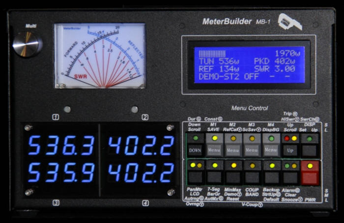
Front Panel - Production Case
The picture below shows the final production case and bezel that is being shipped with the MB-1 kit. The MB-1 below is shown with blue 7-segment LEDs (included in Expansion Kit for orders placed after 5-1-2013)
Rear Panel
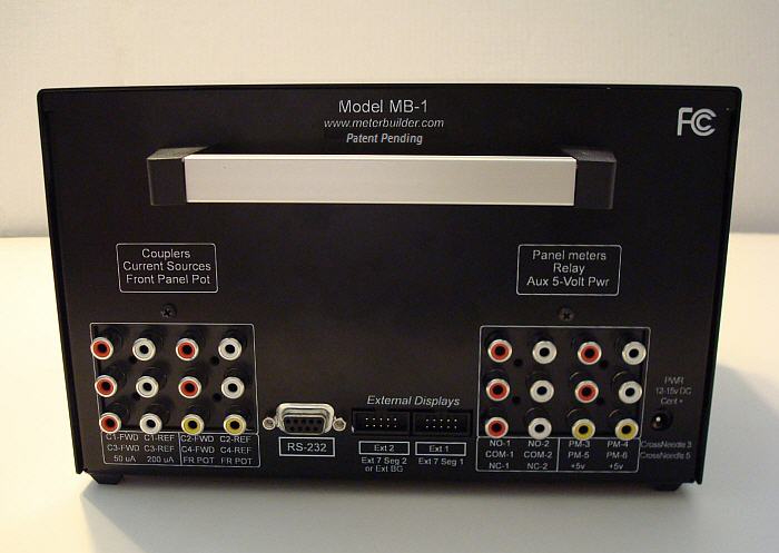
The Rear Panel consists of the following:
Coupler Inputs – Signals from each coupler (power coupler, RF ammeter, or analog sensor) are connected to the RCA jacks on the rear panel.
Panel meter Outputs – Signals to drive user-provided external analog meters are connected to the RCA jacks on the rear panel.
SWR Alarm Jacks – Two sets of double pole - double throw contacts are provided. These may be wired to amplifiers or other devices to control the device when the meter triggers a trip condition. These relay contacts can also be used for specialized control functions when used with analog sensors.
Test Signals – A number of current and voltage sources
are provided to aid you with meter customization and prototyping.
The current sources are used to easily determine the full scale current
rating of an analog meter
movement you may be considering for use with MB-1.
The center tap of the front panel pot (through a protection
resistor) is also made accessible via two rear panel RCA jacks.
These provide a convenient variable 0 - 5 volts DC
signal using the front panel pot.
5 Volt Auxiliary Power – The MB-1 circuitry is powered
with two independent 5 volt busses. One of these busses is
made available
on two of the rear panel RCA jacks providing a convenient source of
power for low current add-ons and prototyping.
RS-232 Interface – This is used to communicate with the following PC utilities:
- Bootloader - to update firmware
- EEPROM Backup/Restore Utility
- Calibration Table Update utility
External Display Interfaces – Up to two hi-visibility external displays (7-segment display modules or Bar Graph modules) are connected via the 10 pin IDC connectors on the rear panel.
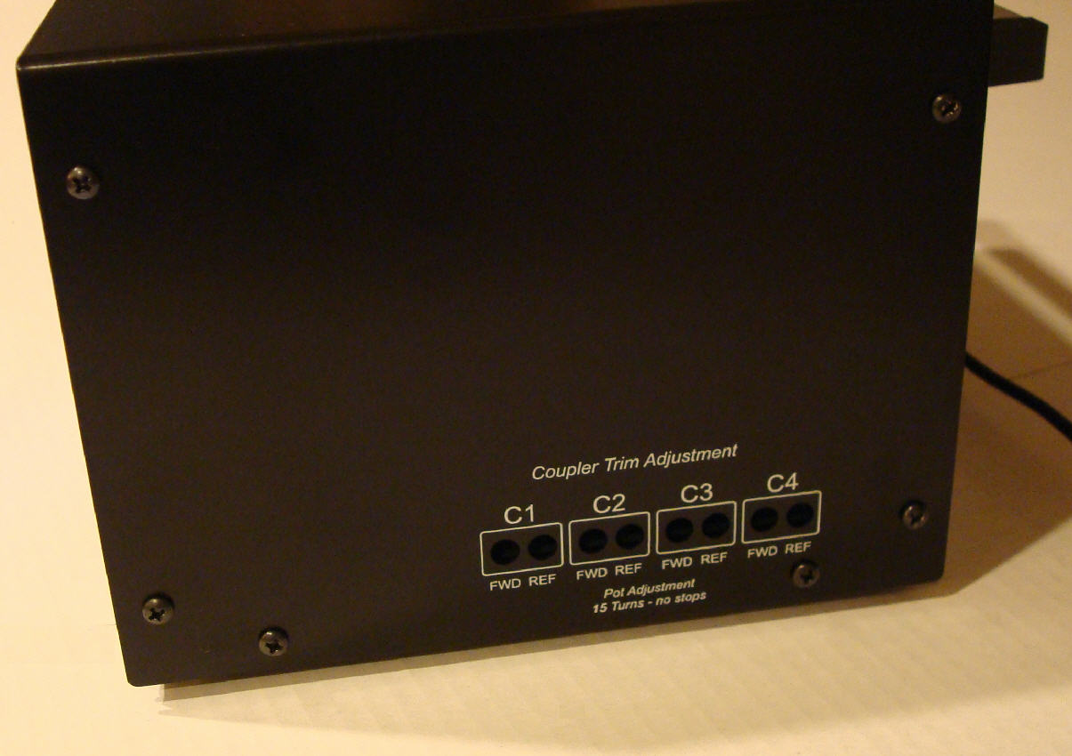
Right Side Panel - Coupler Trim Pots
Eight Coupler trim pots (two for each coupler) are accessible from the right side of the meter. These pots are adjusted during the coupler calibration procedure to provide maximum sensitivity and resolution for a given coupler based on the coupler's sensitivity and the desired full scale value that you specify during set up. The coupler trim pots are high resolution 15 turn pots.
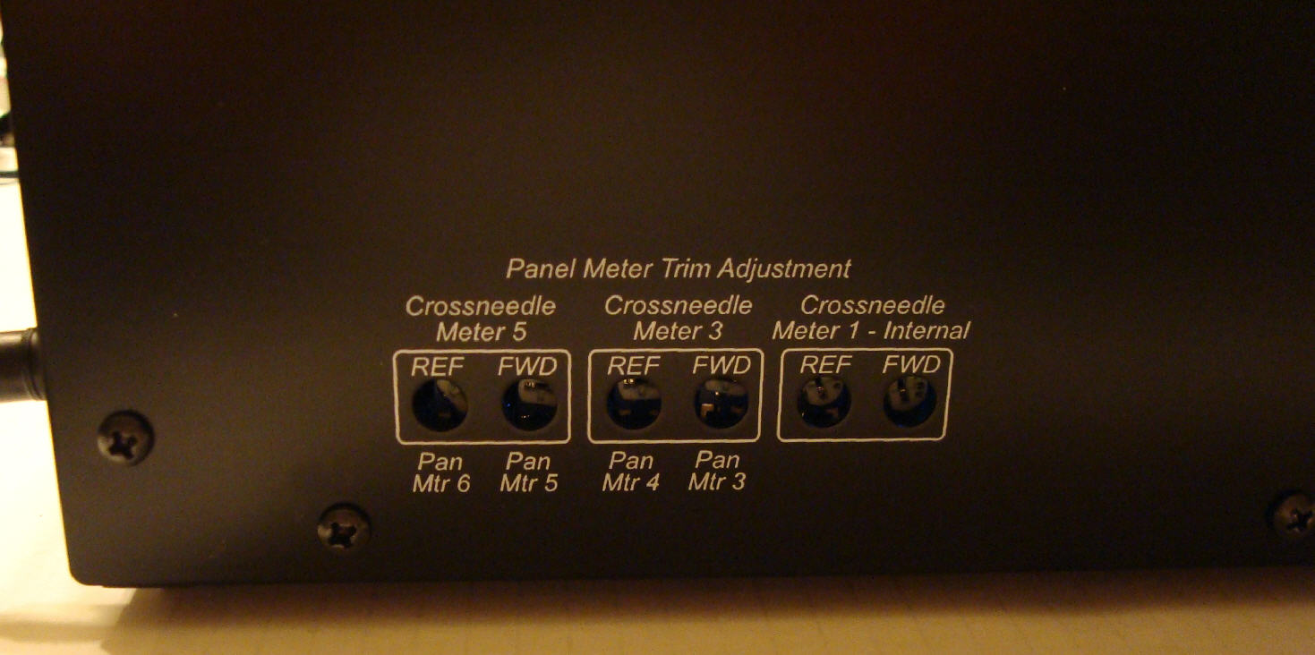
Left Side Panel - Panel Meter Trim Pots
Six Panel Meter trim pots are accessible from the left side of
the meter. These pots are adjusted during panel meter calibration
based on the full scale current rating of the analog meter being calibrated.
Internal View
Expansion Kit
